Wednesday, January 2, 2019

January 02, 2019

No-Load Transformer And Its Phasor Diagram

Before we start discussing about the no-load condition of a transformer, it is important to first understand that what is meant by no-load.
"A transformer is said to be on no-load when the secondary winding of the transformer is left open-circuited thereby reducing the secondary current to zero".

WHAT HAPPENS WHEN TRANSFORMER IS AT NO-LOAD?

During no-load condition, secondary current in the transformer reduces to zero and when an alternating voltage is applied to the primary, a small current I0 flows in the primary winding.
The current I0 is called no-load current of the transformer and it is 3 to 5 percent of the rated primary current.
No-load current is made up of two components Iu and Im.
Iu is called magnetizing component.It magnetizes the core. We can also say that it sets up the flux in the core and therefore Im is in phase with (flux). It is also called reactive or wattless component of no-load current.
The other component Iw supplies the hysteresis and eddy-current losses in the core. It is in the phase with the applied voltage V1. It is also called active or wattful component of no-load current.

Phasor Diagram At No Load

Phasor diagram for a transformer(real) under no-load condition is shown in the fig. below.

The flux  is taken as the reference phasor.  The magnetizing component of the no-load current Im, magnetizes the core i.e, it sets up the flux in the core. Therefore, Im is in phase with the flux.
Iw is in phase with the applied volage, V1.  The phasor sum of Im and Iw is I0. The angle 0, between Iw and I0 is called no-load power factor angle. The power factor on no load is cos(0).
Iw = I0 . cos(0).
Im = I0 . cos(0)
I0 = v{(Iw) + (Im)}
Since, E1 and E2 are induced by the same flux ?, therefore E1 and E2 will be in same phase , but E1 and E2 lags behind the flux ? by 90 degree. E1 = k. E2 (where k = T1/T2,  T1 & T2 are no. of turns on primary and secondary winding)
E1 and V1 will be opposite to each other due to Lenz Law. If the voltage drop in the primary winding are neglected then V1 will be equal and opposite to the E1.
Power input to the transformer during no-load condition is :-
P0 = V1 . I0. cos (0)

Sunday, December 30, 2018

December 30, 2018

Electrical Circuit Fundamentals


Electric Circuit Fundamentals

The Fundamental knowledge and skills of the basic electrical circuits always work as a strong foundation for technically sound experience. Students can also become vigorously familiar with these basic circuits particularly with hands-on experience. The basic circuit thus helps a learner to gain understanding of the basic components and circuit’s characteristics while it is in operation.
This article gives fundamental concepts about two types of electric circuits: AC and DC circuits. Depending on the type of source, electricity varies as Alternating Current (AC) and Direct Current (DC).

Basic DC circuits

In DC circuits, electricity flows in constant direction with a fixed polarity that doesn’t vary with time. A DC Circuit uses steady current components like resistors and resistor combinations; transient components like inductors and capacitors; indicating meters like moving coil voltmeters and ammeters; power supply battery sources, and so on.
For analyzing these circuits, different tools like ohms law, voltage and current laws like KCL, KVL, and network theorems like Thevinens, Norton's, Mesh analysis, etc are used. The following are some of the basic DC circuits that express the operating nature of a DC circuit.

Series and Parallel Circuits


Resistive loads represent the lighting loads that are connected in various configurations to analyze the DC circuits that are shown in the figure. The way of connecting loads certainly changes the circuit characteristics.

In a simple DC circuit, a resistive load as a bulb is connected between the positive and negative terminals of the battery. The battery supplies the required power to the bulb and allows a user to place a switch to turn on or off according to the requirement.

The loads or resistances connected in series with the DC source, as an electrical symbols for lighting load, circuit share common current, but the voltage across the individual loads vary and is added to get the total voltage. So there is a voltage reduction at the end of the resistor compared to the first element in series connection. And, if any load goes out from the circuit, the entire circuit will be open circuited.

In a parallel configuration, the voltage is common for each load, but the current varies depending on the rating of the load. There is no problem in an open circuit even if one load is out of the circuit. Many load connections are of this type, for instance the home wiring connection.

Therefore, from the above circuits and figures, one can easily find the total load consumption, voltage, current and the power distribution in a DC circuit.

AC Circuit with a Resistor

In this type of circuit, the voltage dropping across the resistor is exactly in phase with the current as shown in the figure. This means that when instantaneous value voltage is zero, the current value at that instant is also zero. And also, when the voltage is positive during the positive half wave of the input signal, the current is also positive, so the power is positive even when they are in negative half wave of the input. This means that the AC power in a resistor is always dissipating as heat while taking it from the source, irrespective of whether the current is positive or negative.

AC Circuit with Inductors

Inductors oppose the change in the current through them not like the resistors that oppose the flow of current. This means when the current is increased, the induced voltage tries to oppose this change of the current by dropping the voltage. The voltage dropped across an inductor is proportional to the rate of change in the current.
Therefore, when the current is at its maximum peak (no rate of change in shape), the instantaneous voltage at that instant is zero, and reverse happens when the current peaks at zero (maximum change of its slope), as shown in the figure. So there is no net power dissipation in the inductor AC circuit.
Thus, the instantaneous power of the inductor, in this circuit, is entirely different from the DC circuit, where it is in same phase. But, in this circuit, it is 90 degrees apart so the power is negative, at times, as shown in the figure. Negative power means the power releases back to the circuit as it absorbs it in the rest of the cycle. This opposition of current change is called as reactance, and it depends on the frequency of the operating circuit.

AC Circuit with Capacitors

A Capacitor opposes a change in the voltage, which is dissimilar to an inductor that opposes a change in the current. By supplying or drawing current, this type of opposition takes place, and this current is proportional to the rate of change of the voltage across the capacitor.

Here, the current through the capacitor is the result of the change in the voltage in the circuit. Therefore, the instantaneous current is zero when the voltage is at its peak value (no change of voltage slope), and it is maximum when the voltage is at zero, so the power also alternates in positive and negative cycles. This means it does not dissipate the energy but just absorbs and releases the power.

AC circuit behavior can also be analyzed by combining the above circuits like RL, RC and RLC Circuits in series as well as in parallel combinations. And also the equations and formulas of the above circuits are exempted in this article to reduce the complexity, but the overall idea is to give a basic concept about the electrical circuits.

We hope that you might have understood these basic electrical circuits, and would like to have further hands-on experience on various electrical and electronic circuits. For any of your requirements, comment in the comments section given below. We are always ready to help you guide in this particular area of your choice.
Other Articles to Read
What is charge particles and electrical current
Electrical fault current and its types
What is meant by an electrical stray current
What is an electrical eddy current
What is electrical skin effect in power system
What is electrical proximity effect in power system
What is an electrical corona effect in power system
Electrical Basic Concept MCQs
MCQ on Electrical DC Circuits
MCQ on Electrical Network Theorem
Electrical DC Generator
Electrical DC Motor
DC Generator Interview Questions
MCQ on DC Generator
DC Motor Interview Questions
MCQ on DC Motor
MCQ on Electrostatics
Kirchhoff’s Voltage Law (KVL) Kirchhoff’s Circuit Laws
Kirchhoff’s Current Law (KCL) Kirchhoff’s Circuit Laws
Half Wave Rectifier AC/DC Converter
Full Wave Rectifier And Its Types AC/DC Converter
Diode Clampers – Clamping Circuits
Arduino Self Balancing Robot – Smartphone Control
Arduino Quadcopter Drone
DIY Adruino Based Solar Tracker
Waste Water Engineering, Treatment and Reuse | Metcalf & eddy
Distribution System Modeling and Analysis | Kersting & William H
Arduino Home Work Writing Machine
Electric Power Distribution Engineering | Turan Gonen
Online Electrical Engineering MCQs Test
Online Transmission Lines And Cable MCQs Test
Online High Voltages MCQs Test
Online DC Generator MCQs Test
Online DC Motor MCQs Test

Saturday, October 20, 2018

October 20, 2018

H-Parameter Of Two Port Network

In this article we will study about h-Parameter of two port network.
h-Parameter representation is widely used in modelling of electronic components and circuits, particularly transistors.
h-Parameter is called "Hybrid Parameter".
In h-Parameter, the input voltage and output current are function of input current and output voltage respectively.
( V1 , I2 ) = f ( I1 , V2 )
In matrix form,
[V1] =    [h11  h12]   [I1]
[I2] =     [h21  h22]   [V2]
Writing it in equation,
V1 = h11* I1 + h12* V2 .........eq1
I2 =  h21* I1 + h22* V2 .........eq2
CASE-1 SHORT CIRCUITING THE OUTPUT PORT
If the Output port of the two port network is  short circuited then output voltage is zero, i.e. V2 = 0.
H parameter
Now, equation 1 and 2 will be reduced to :
V1 = h11* I1
I2 =  h21* I1
So, h11 = I1 /V1    ( keeping V2 = 0 )
      h21 = I2/ V1    ( keeping V2 = 0 )
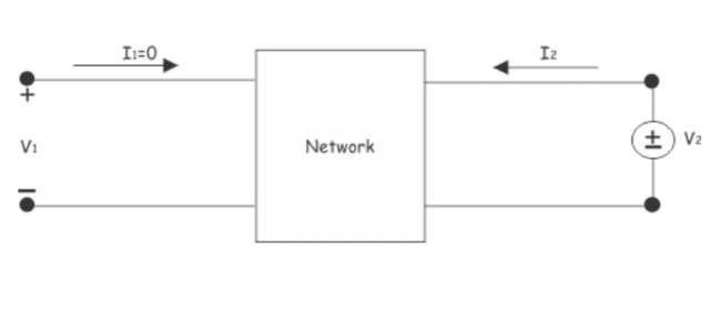
CASE-2 OPEN CIRCUITING THE INPUT PORT
If the Input port of the two port network is open circuted then the input current is zero, i.e. I1 = 0.
H parameter
Now, equation 1 and 2 will be reduced to :
V1 = h12* V2
I2 =  h22* V2
So, h12 = V1/ V2    ( keeping I1= 0 )
      h22 = V2/ I2   ( keeping  I1 = 0 )
h11 is called input impedance and its unit is ohm.
h12 is called forward current gain and is unitless.
h21 is called reverse voltage and is unitless.
h22 is called output impedance and its unit is mho.
For a network to be symmetrical,
h11*h22 - h12*h21 = 0. (h=0)
For a network to be reciprocal,  h12 = -h21
EQUIVALENT CIRCUIT OF Y-PARAMETER
Equivalent circuit of H parameter

Friday, October 19, 2018

October 19, 2018

Y-PARAMETER of Two Port Network

In this article we will study about Y Parameter of two port network.
Y-Parameter is also called "Short Circuit Parameter" and "Admittance Parameter".
In Y-Parameter, the input and output currents are function of input and output Voltages.
( I1 , I2 ) = f ( V1 , V2 )
It can also be written as:
[I] = [Y]   [V]
where [Y] represents Admittance Matrix.
In matrix form,
[I1] =    [Y11  Y12]   [V1]
[I2] =    [Y21  Y22]   [V2]
Writing it in equation,
I1 = Y11* V1 + Y12* V2 .........eq1
I2 = Y21* V1 + Y22* V2 .........eq2
CASE-1 SHORT CIRCUITING THE OUTPUT PORT
If the Output port of the two port network is  short circuited then output voltage is zero, i.e. V2 = 0.
Y Parameter
Now, equation 1 and 2 will be reduced to :
I1 = Y11* V1
I2 = Y21* V1
So, Y11 = I1 /V1    ( keeping v2 = 0 )
      Y21 = I2/ V1    ( keeping V2 = 0 )
CASE-2 SHORT CIRCUITING THE INPUT PORT
If the Input port of the two port network is short circuited then the input voltage is zero, i.e. V1 = 0.
Y Parameter
Now, equation 1 and 2 will be reduced to :
I1 = Y12* V2
I2 = Y22* V2
So, Y12 = I1/ V2    ( keeping V1= 0 )
       Y22 = I2/ V2  ( keeping V1 = 0 )
Y11 is called input driving point Admittance.
Y12 is called forward transfer Admittance.
Y21 is called reverse transfer Admittance
Y22 is called output driving point Admittance.
For a network to be symmetrical , Y11 = Y22
For a network to be reciprocal, Y12 = Y21
EQUIVALENT CIRCUIT OF Y-PARAMETER
Equivalent circuit of Y Parameter

Monday, October 15, 2018

October 15, 2018

Z-Parameter Of Two Port Network

In this article we will study about Z Parameter of two port network.
Z-Parameter is also called "Open Circuit Parameter" and "Impedance Parameter".
In Z-Parameter, the input and output voltage are function of input and output current.
( V1 , V2 ) = f ( I1 , I2 )
It can also be written as:
[V] = [Z][I]
Where Z represents Impedance Matrix.
In matrix form
[V1] =    [Z11  Z12]   [I1]
[V2] =    [Z21  Z22]   [I2]
Writing it in equation,
V1 = Z11* I1 + Z12* I2 .........eq1
V2 = Z21* I1 + Z22* I2 .........eq2
CASE-1 OPEN CIRCUITING THE OUTPUT PORT
If the Output port of the two port network is open circuited then the output current is zero, i.e. I2 = 0.
Now, equation 1 and 2 will be reduced to :
V1 = Z11* I1
V2 = Z21* I1
So, Z11 = V1/ I1    ( keeping I2 = 0 )
Z21 = V2/ I1  ( keeping I2 = 0 )
CASE-2 OPEN CIRCUITING THE INPUT PORT
If the Input port of the two port network is open circuited then the input current is zero, i.e. I1 = 0.
Now, equation 1 and 2 will be reduced to :
V1 = Z12* I2
V2 = Z22* I2
So, Z12 = V1/ I2    ( keeping I1 = 0 )
Z22 = V2/ I2  ( keeping I1 = 0 )
Z11 is called input driving point Impedance
Z12 is called forward transfer Impedance
Z21 is called reverse transfer Impedance
Z22 is called output driving point Impedance.
For a network to be symmetrical , Z11 = Z22
For a network to be reciprocal, Z12 = Z21
EQUIVALENT CIRCUIT OF Z-PARAMETER

Monday, September 3, 2018

September 03, 2018

Speed Control Method Of DC Motor

In this article we will study about the speed control of dc series motor.
There are some popular methods of speed control of dc series motor are:

  • Variation of armature resistance. This method is called armature resistance control.
  • Variation of field flux. This method is called field flux control.

ARMATURE RESISTANCE CONTROL

In this case, a external resistance Re is connected in the armature circuit of the dc series motor. When the value of the external resistance is increased, it will cause increased voltage drop. Hence the effective voltage across the armature circuit will be reduced.

Speed will also reduced. So the speed of the motor can be controlled by varying the resistance.  As the value of Re is increased then motor will run at lower speed.
This method suffers from some serious drawbacks:

  • A large amount of power is wasted in the external resistance.
  • Speed can only be reduced below the normal speed with this method. It cannot be used for increase of speed.
FIELD FLUX CONTROL
In this method , a variable resistance called diverter, Rd is connected in parallel across the series field winding. This resistance reduces the current flowing through the series field winding and it results in lesser field flux. Since the speed is inversely proportional to the field flux , so the speed of the motor will increase.
If the value of diverter resistance is decreased then more current will flow through it instead of series field winding and lesser flux will produce which will increase the speed of the motor.
This can also be achieved by providing a tapped series field winding, which is most commonly used for traction purposes.

Saturday, August 18, 2018

August 18, 2018

Hot Wire Instrument, Working | Advantages & Disadvantages

In this article we will study about the Hot Wire Instruments, it construction , working , advantages and disadvantages.
These type of instruments are mainly used as Ammeter but can be used as Voltmeter by connecting a high resistance in series.

CONSTRUCTION OF HOT WIRE INSTRUMENT

As shown in the figure , this type of instrument consists of a wire AB which is made up of platinum-iridium because it can withstand oxidation at higher temperature. Wire AB is stretched between a fixed end B and adjusting screw at A. When current is to be measured , it is then passed through the wire AB.
Diagram of hot wire instruments

There is a another wire CD which is usually made up of phosphor-bronze. One end of wire CD is is attached to the center of AB while other end of CD is taken over the pulley by silk thread. This silk thread is pulled by the spring S.

WORKING OF HOT-WIRE INSTRUMENT

Working principle of hot wire instrument is based upon the heating effect of Electric Current. When the current is passed through the wire AB , it expands. This produces the sag in wire AB , since the wire CD is attached to AB. So it will produce a slack in CD, this slack in CD is taken up by the silk thread which after passing through the pulley is attached to the spring. As soon as the silk thread is pulled by the spring, the pulley moves , therefore produces a deflection in the pointer which in turn gives the reading on calibrated scale.
It can be seen that the deflection of the pointer is proportional to the extension of wire AB which is proportional to the  square of the current (I(2)).
Damping :  Generally eddy current damping is provided in hot wire instrument. A thin light aluminium disc is attached to the pulley such that it moves between the poles of permanent damping magnet ,M.

ADVANTAGES OF HOT WIRE INSTRUMENTS


  • Such instruments can be used for both a.c and d.c.
  • There readings are independent of waveform and frequency.
  • They are not affected by the stray magnetic field.

DISADVANTAGES OF HOT WIRE INSTRUMENTS


  • They have high power consumption.
  • They are fragile.
  • Hot wire instruments are sluggish (slow) in nature i.e. it takes time to heat up.